This component is obsolete and its use in filters is not recommended. Use the recent version of the component.
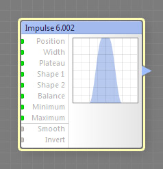
The Impulse component generates an impulse curve composed of two slopes (which can be smooth or linear) and a flat segment between them (the plateau). This is a curve component, it can be located in the Curves category on the Components Bar.
Position: Map Input
Defines the position of the impulse center. Negative values shift the impulse center leftwards; positive values shift it rightwards. With Position of -100 and 100, the entire impulse is positioned beyond the visible range of the curve. Since Position is a map input, its value can be controlled separately for different image areas by connecting a map component to this input.
Width: Map Input
Defines the width of the impulse, including both its slopes and the flat segment between them (the plateau). With Width of 0, the impulse is completely eliminated. With Width of 100, the impulse occupies the entire visible range (provided that Position is set to 0). Since Width is a map input, its value can be controlled separately for different image areas by connecting a map component to this input.
Plateau: Map Input
Defines the width of the flat segment between the slopes of the impulse (the plateau). The value of 0 eliminates the plateau, in this case the impulse is formed by slopes only. With Plateau of 100, the entire impulse is flat and the slopes are completely eliminated. Since Plateau is a map input, its value can be controlled separately for different image areas by connecting a map component to this input.
Shape 1: Map Input
Adjusts the shape of the left slope of the impulse. Technically, this is done by remapping the amplitude of the slope segment with a Bias curve. Negative values make the slope more concave; positive values make it more convex. Since Shape 1 is a map input, its value can be controlled separately for different image areas by connecting a map component to this input.
Shape 2: Map Input
Adjusts the shape of the right slope of the impulse. Technically, this is done by remapping the amplitude of the slope segment with a Bias curve. Negative values make the slope more concave; positive values make it more convex. Since Shape 2 is a map input, its value can be controlled separately for different image areas by connecting a map component to this input.
Balance: Map Input
Defines the tilt of the impulse. Values below 50 tilt the impulse leftwards, values above 50 tilt it rightwards. Technically, this parameter shifts the plateau segment within the impulse width, altering the width of the both slopes. Therefore, with Balance of 0 the left slope is completely eliminated, and with Balance of 100 the right slope is eliminated. Since Balance is a map input, its value can be controlled separately for different image areas by connecting a map component to this input.
Minimum and Maximum: Map Inputs
Minimum and Maximum define the output range of the curve. When the Minimum value is greater than the Maximum value, they get reversed – the Minimum parameter defines the Maximum value and vice versa. This is needed to avoid turning the curve upside down. Since Minimum and Maximum are map inputs, their values can be controlled separately for different image areas by connecting a map component to any of these inputs.
When turned on, the impulse slopes are smooth, otherwise they are linear.
Inverts the curve, converting its value at each point to its opposite: 0.05 to 0.95, 0.25 to 0.75 etc. Invert is applied to the curve before Minimum and Maximum take effect, so they still define the output range correctly.