This component is obsolete and its use in filters is not recommended. Use the recent version of the component.
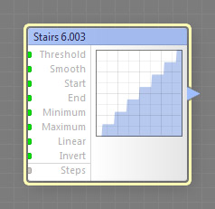
The Stairs component generates a stair-shaped curve with an adjustable number of steps. Depending on the width of the transition zone between the steps (specified by the Smooth parameter), the transition can be smooth or sharp. This is a curve component, it can be located in the Curves category on the Components Bar.
Threshold: Map Input
Sets the positions of the center of the transition from each step of the curve to the next one. Smaller values shift the transition centers to the left, greater values shift them to the right. When Threshold is set to 0 or 100, Smooth has no effect. Since Threshold is a map input, its value can be controlled separately for different image areas by connecting a map component to this input.
Smooth: Map Input
Defines the width of the transition zone between the curve steps. When set to 0, the transition zone has zero width, which makes the transition sharp. In this case, the Linear parameter has no effect. Since Smooth is a map input, its value can be controlled separately for different image areas by connecting a map component to this input.
Note that the actual width of the transition zone also depends on the Threshold value. If the resulting zone exceeds the width of one step of the curve, the transition zone is clipped so that it fits into one curve step and is still centered around the center point specified by Threshold. For example, if the transition zone center is set to 10, and Smooth is set to 40, the resulting range will be -10 to 30, which will be clipped to the range of 0 to 20.
Start and End: Map Inputs
Start and End define the starting and ending points of the curve. When the Start value is greater than the End value, they get reversed – the Start parameter defines the End value and vice versa. This is needed to avoid flipping the curve horizontally. Since Start and End are map inputs, their values can be controlled separately for different image areas by connecting a map component to any of these inputs.
Minimum and Maximum: Map Inputs
Minimum and Maximum define the output range of the curve. When the Minimum value is greater than the Maximum value, they get reversed – the Minimum parameter defines the Maximum value and vice versa. This is needed to avoid turning the curve upside down. Since Minimum and Maximum are map inputs, their values can be controlled separately for different image areas by connecting a map component to any of these inputs.
Invert: Map Input
Inverts the curve, converting its value at each point to its opposite: 0.05 to 0.95, 0.25 to 0.75 etc. Invert is applied to the curve before Minimum and Maximum take effect, so they still define the output range correctly. When a map component is connected to this input, the state of the checkbox is determined separately for different image areas by the brightness level of the image supplied by that component. The brightness level of 0 to 50 corresponds to unchecked Invert, and the level of 50 to 100 corresponds to checked Invert.
Linear: Map Input
When turned on, the transition between the steps is linear, otherwise it is smooth. This parameter has no effect when Smooth is set to 0. When a map component is connected to this input, the state of the checkbox is determined separately for different image areas by the brightness level of the image supplied by that component. The brightness level of 0 to 50 corresponds to unchecked Linear, and the level of 50 to 100 corresponds to checked Linear.
Defines the number of the steps in the range of 1 to 20.