This component is obsolete and its use in filters is not recommended. Use the recent version of the component.
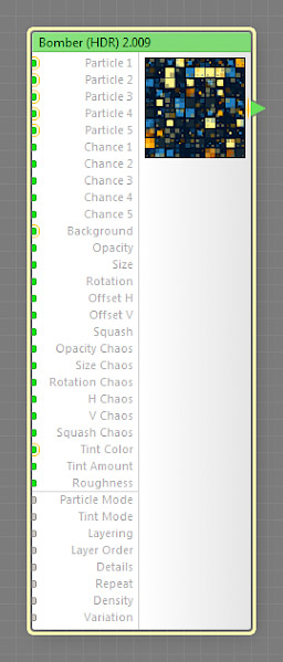
The Bomber (HDR) component sprays particles in a controlled manner. This is a map component, it can be located in the Patterns category on the Components Bar. Bomber (HDR) is a discrete component: any filter that uses it is automatically classed as a discrete filter. This component can output HDR colors.
Technically, the output image produced by this component is composed of multiple particle layers, which are organized in a way similar to fractal noise components such as Perlin Noise. The number of particle layers is controlled by the Details input, and their relative transparency by the Roughness input. Each particle layer is a regular grid with the cell size is controlled by the Repeat input, where each cell houses 1 to 25 particles, depending on the value of the Density input. As with fractal noises, the width of the grid cell of a particular layer is 2 times smaller than that of the previous layer. By default, a single particle is placed at the center of each grid cell, but its position, as well as the opacity, rotation angle, size, offset and other parameters, can be fine-tuned, randomized or mapped with other components.
Bomber (HDR) is very similar to the Bomber component which doesn't support HDR colors but has more blending modes for compositing and tinting particles.
Particle 1 – Particle 5: Map Inputs (HDR)
These inputs specify particles to be sprayed. If the Image component is used as a particle source, it is recommended to set its Mode parameter to Particle to ensure correct reaction to the changes of the global Size. These inputs can accept HDR colors. Particle 1 – Particle 5 are so-called 'seamlessizer inputs' – they can safely accept connections from non-seamless components without preventing the resulting filter from generating seamlessly-tiled results.
Chance 1 – Chance 5: Map Inputs
These inputs define the chance of a specific particle to appear in the output image. Since Chance 1 – Chance 5 are map inputs, their values can be controlled separately for different image areas by connecting a map component.
Defines the background image. This input can accept HDR colors.
Opacity: Map Input
Defines the opacity of the particles. Lower values make particles more transparent, and Opacity of 0 makes them completely invisible.
Since Opacity is a map input, it allows you to control the opacity of individual particles separately. When a map component is connected to this input, the opacity of each individual particle is determined by the brightness level of the image supplied by that component. The brightness level defining the particle opacity is sampled at the center of that particle (particles are considered square, regardless of their actual shape.) Black areas correspond to Opacity of 0, white areas to Opacity of 100, and the opacity values in-between are represented by intermediate brightness levels.
The resulting opacity of each particle is also affected by Opacity Chaos, Particle Mode, Layering, Layer Order, Details and Roughness, as well as the alpha channel of the particles themselves.
Size: Map Input
Controls the size of all the particles. With Size of 0, the particles disappear altogether; with Size of 100, the particles occupy the whole area of the corresponding grid cell.
Since Size is a map input, it allows you to control the size of individual particles separately. When a map component is connected to this input, the size of each individual particle is determined by the brightness level of the image supplied by that component. The brightness level defining the particle size is sampled at the center of that particle (particles are considered square, regardless of their actual shape.) Black areas correspond to Size of 0, white areas to Size of 100, and the size values in-between are represented by intermediate brightness levels.
Rotation: Map Input
Specifies the angle of particle rotation in degrees. Rotation is performed around the center of each particle (the particles are considered square regardless of their actual shape.)
Since Rotation is a map input, it allows you to control the rotation angle of individual particles separately. When a map component is connected to this input, the rotation angle for each individual particle is determined by the brightness level of the image supplied by that component. The brightness level defining the particle rotation angle is sampled at the center of that particle (particles are considered square, regardless of their actual shape.) Black areas correspond to Rotation of 0, white areas to Rotation of 100, and the angle values in-between are represented by intermediate brightness levels.
Offset H: Map Input
Specifies the amount of horizontal shift. When Offset H is 0, particles are horizontally centered within their grid cells. Positive values move the particles rightwards, while negative values move them leftwards. The particle center can't go beyond the edges of its grid cell.
Since Offset H is a map input, it allows you to control the amount of shift for individual particles separately. When a map component is connected to this input, the amount of shift for each individual particle is determined by the brightness level of the image supplied by that component. The brightness level defining the particle offset is sampled at the center of that particle (particles are considered square, regardless of their actual shape.) Black areas correspond to Offset H of -100, white areas to Offset H of 100, and the offset values in-between are represented by intermediate brightness levels.
Offset V: Map Input
Specifies the amount of vertical shift. When Offset V is 0, particles are vertically centered within their grid cells. Positive values move the particles downwards, while negative values move them upwards. The particle center can't go beyond the edges of its grid cell.
Since Offset V is a map input, it allows you to control the amount of shift for individual particles separately. When a map component is connected to this input, the amount of shift for each individual particle is determined by the brightness level of the image supplied by that component. The brightness level defining the particle offset is sampled at the center of that particle (particles are considered square, regardless of their actual shape.) Black areas correspond to Offset V of -100, white areas to Offset V of 100, and the offset values in-between are represented by intermediate brightness levels.
Squash: Map Input
Specifies how the particles are squashed, i.e. the non-uniformity of flattening along the axes. Squashing is performed around the center of each particle (the particles are considered square regardless of their actual shape.) The value of 0 corresponds to the original undistorted particle shape, negative values squash the particles horizontally, and positive values squash them vertically.
Since Squash is a map input, it allows you to control the amount of squashing for individual particles separately. When a map component is connected to this input, the amount of squashing for each individual particle is determined by the brightness level of the image supplied by that component. The brightness level defining the particle squashing is sampled at the center of that particle (particles are considered square, regardless of their actual shape.) Black areas correspond to Squash of -100, white areas to Squash of 100, and the squashing values in-between are represented by intermediate brightness levels.
Opacity Chaos: Map Input
Defines the amount of randomization applied to the opacity of each particle. With Opacity Chaos of 0, no randomization is applied; Opacity Chaos of 100 corresponds to the highest randomization level.
Since Opacity Chaos is a map input, it allows you to control the amount of opacity randomization applied to individual particles separately. When a map component is connected to this input, the amount of randomization for each individual particle is determined by the brightness level of the image supplied by that component. The brightness level defining the randomization amount is sampled at the center of that particle (particles are considered square, regardless of their actual shape.) Black areas correspond to Opacity Chaos of 0, white areas to Opacity Chaos of 100, and the randomization values in-between are represented by intermediate brightness levels.
Size Chaos: Map Input
Defines the amount of randomization applied to the size of each particle. With Size Chaos of 0, no randomization is applied; Size Chaos of 100 corresponds to the highest randomization level.
Since Size Chaos is a map input, it allows you to control the amount of size randomization applied to individual particles separately. When a map component is connected to this input, the amount of randomization for each individual particle is determined by the brightness level of the image supplied by that component. The brightness level defining the randomization amount is sampled at the center of that particle (particles are considered square, regardless of their actual shape.) Black areas correspond to Size Chaos of 0, white areas to Size Chaos of 100, and the randomization values in-between are represented by intermediate brightness levels.
Rotation Chaos: Map Input
Defines the amount of randomization applied to the rotation angle of each particle. With Rotation Chaos of 0, no randomization is applied; Rotation Chaos of 100 corresponds to the highest randomization level.
Since Rotation Chaos is a map input, it allows you to control the amount of rotation randomization applied to individual particles separately. When a map component is connected to this input, the amount of randomization for each individual particle is determined by the brightness level of the image supplied by that component. The brightness level defining the randomization amount is sampled at the center of that particle (particles are considered square, regardless of their actual shape.) Black areas correspond to Rotation Chaos of 0, white areas to Rotation Chaos of 100, and the randomization values in-between are represented by intermediate brightness levels.
H Chaos: Map Input
Defines the amount of randomization applied to the horizontal shift of each particle. With H Chaos of 0, no randomization is applied; H Chaos of 100 corresponds to the highest randomization level.
Since H Chaos is a map input, it allows you to control the amount of shift randomization applied to individual particles separately. When a map component is connected to this input, the amount of randomization for each individual particle is determined by the brightness level of the image supplied by that component. The brightness level defining the randomization amount is sampled at the center of that particle (particles are considered square, regardless of their actual shape.) Black areas correspond to H Chaos of 0, white areas to H Chaos of 100, and the randomization values in-between are represented by intermediate brightness levels.
V Chaos: Map Input
Defines the amount of randomization applied to the vertical shift of each particle. With V Chaos of 0, no randomization is applied; V Chaos of 100 corresponds to the highest randomization level.
Since V Chaos is a map input, it allows you to control the amount of shift randomization applied to individual particles separately. When a map component is connected to this input, the amount of randomization for each individual particle is determined by the brightness level of the image supplied by that component. The brightness level defining the randomization amount is sampled at the center of that particle (particles are considered square, regardless of their actual shape.) Black areas correspond to V Chaos of 0, white areas to V Chaos of 100, and the randomization values in-between are represented by intermediate brightness levels.
Squash Chaos: Map Input
Defines the amount of randomization applied to the squashing of each particle. With Squash Chaos of 0, no randomization is applied; Squash Chaos of 100 corresponds to the highest randomization level.
Since Squash Chaos is a map input, it allows you to control the amount of squashing randomization applied to individual particles separately. When a map component is connected to this input, the amount of randomization for each individual particle is determined by the brightness level of the image supplied by that component. The brightness level defining the randomization amount is sampled at the center of that particle (particles are considered square, regardless of their actual shape.) Black areas correspond to Squash Chaos of 0, white areas to Squash Chaos of 100, and the randomization values in-between are represented by intermediate brightness levels.
Specifies a tint color to be applied to the particles. Technically, tinting is implemented by blending the particle image with the color supplied by Tint Color using the blending mode specified by the Tint Mode input and the opacity specified by the Tint Amount input. This input can accept HDR colors. Connecting a map component to the Tint Color input allows you to control the tint color for each particle separately. In this case, the tint color to apply to each particle is sampled at the center of that particle (particles are considered square, regardless of their actual shape.)
Tint Amount: Map Input
Specifies the amount of tinting to be applied to the particles. Technically, Tint Amount specifies the opacity used for blending the particle image with the color supplied by Tint Color.
Since Tint Amount is a map input, it allows you to control the tint amount for individual particles separately. When a map component is connected to this input, the tint amount for each individual particle is determined by the brightness level of the image supplied by that component.The brightness level defining the tint amount is sampled at the center of that particle (particles are considered square, regardless of their actual shape.) Black areas correspond to Tint Amount of 0, white areas to Tint Amount of 100, and the tint amount values in-between are represented by intermediate brightness levels.
Roughness: Map Input
Adjusts the roughness of the particle pattern. Technically, Roughness defines the relative transparency of the particle layers (the number of the layers is controlled by the Details parameter). Roughness of 0 sets all layers but the first to zero transparency, which is equivalent to setting the Details parameter to 0. Low roughness values give layers with large-grained grids more visibility. Higher roughness values increase the visibility of layers with smaller-grained grids, making the resulting pattern rougher. Roughness has no effect when Details is set to 0, because in this case only one particle layer is visible. The relative transparency of the particle layers is also affected by the Layering input.
Since Roughness is a map input, its value can be controlled separately for different image areas by connecting a map component to this input. Lower Roughness can speed up the rendering – when the visibility of smaller-grained particle layers is very close to zero, they are 'turned off' to save the rendering time.
Specifies the blending mode used for blending the particle layers with the Background. The following modes are available: Normal, Darken, Multiply, Lighten, Linear Dodge, Difference, Hue, Saturation, Color, and Luminosity. For more information on how each mode works, see Blend (HDR). Due to the support of HDR colors the number of blending modes supported by this component is less than that of the Bomber component.
Specifies the blending mode for particle tinting. This mode is used for blending the particles with the color supplied by Tint Color and opacity specified by Tint Amount. The following modes are available: Normal, Darken, Multiply, Lighten, Linear Dodge, Difference, Hue, Saturation, Color, and Luminosity. For more information on how each mode works, see Blend (HDR). Due to the support of HDR colors the number of blending modes supported by this component is less than that of the Bomber component.
Specifies the way the Details and Roughness inputs affect the relative transparency of particle layers.
The Balanced mode calculates the layer transparencies using the same algorithm as used in fractal noises such as Perlin Noise. This mode is recommended for making noise-like patterns and for use in situations where changing the Roughness value should not significally affect the average brightness of the resulting image.
Both Simple and Simple (Normalized) modes arrange the relative transparencies of the particle layers in a linear progression, where the first layer (one with the largest-grained grid) is always fully opaque, and the opacity of each subsequent layer decreases by a linear decrement which depends on the Roughness value (and also, in case of Simple (Normalized), on the Details value.) The difference between Simple and Simple (Normalized) is that the former doesn't normalize the transparencies, while the latter normalizes them based on the actual number of visible particle layers (determined by the Details input.)
Specifies the blending order of the particle layers: Small on top or Big on top. When Small on top is selected, the particle layers with smaller-grained grids are successively placed over the layers with larger grids, and vice versa. Note that Big and Small refer to the cell size of the particle grid, not to the actual size of the particle itself.
Adjusts the particle pattern complexity. Technically, Details sets the number of the particle layers that form the resulting pattern. Details of 0 means only the first layer is visible, 20 means 3 layers, and 100 means 11 layers are visible. Values such as 27 mean that first three layers have full visibility, and the fourth one has 70% visibility. Details has no effect when Roughness is set to 0, because in this case only the first layer has 100% visibility no matter how many layers are active.
Large Details value leads to longer rendering times because it increases the number of particle layers, and therefore particles, to calculate. For example, when Details is 0, only one particle layer is rendered. When Details is 100, eleven layers are rendered which can slow down the rendering up to eleven times. So if you don't need a high number of layers, you can lower it to make rendering quicker.
Specifies the number of cells in the layer with the largest-grained particle grid. The subsequent grid will have four times less cells than the first one, and so on. The actual number of repetitions within the output image is also affected by the global Size parameter and the image dimensions.
Specifies the number of particles per grid cell of the particle layer. The actual number of the particles in a single cell equals the square of the Density value – for example, the Density of 2 gives 4 particles per cell, Density of 3 gives 9 particles per cell, etc. Higher Density values may increase the rendering time.
Variation, technically known as random seed, affects the random aspects of the component which cannot be controlled directly: it randomizes the opacity, size, rotation, squashing and shift of the particles when Opacity Chaos, Size Chaos, Rotation Chaos, H Chaos, V Chaos and Squash Chaos are set to non-zero. The randomization is also affected by the global Variation value. For more information, see How Variation Works.