This component is obsolete and its use in filters is not recommended. Use the recent version of the component.
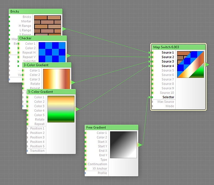
The Map Switch component is a selector that allows switching between several subtrees. Its purpose and function are similar to that of the Switch component. However, there is one important difference: the Selector input of Map Switch is a map input.
The fact that its Selector input is mappable makes this component especially useful in combination with slave-supporting components: slaves can be connected to its Selector input. For example, when used together with Bomber Plus, Map Switch allows you to assemble several particle subtrees, connect them to Source inputs, and switch between them per particle using the Randomizer slave component of Bomber Plus.
In addition to “hard” (discrete) switching where only a single source input is sent to the output, the component allows “soft” (continuous) switching, where selector values that “fall between” integer source numbers are used for interpolating the adjacent sources to produce the output image.
Map Switch is a map component, it is located in the Processing category on the Components Bar. This component can output HDR colors.
Source 1, Source 2, ..., Source 10: Map Inputs (HDR)
These inputs provide the colors or images to be sent to the component's output, depending on the values of the Selector, Max Source and Mode inputs. These inputs can accept HDR colors.
Selector: Map Input
Specifies which of the Source inputs goes to the output, or, when Mode is set to Continuous, which pair of Sources is used to produce the output.
When Mode is set to any Discrete setting, the value of zero corresponds to Source 1, the value of 100 to the Source input defined by Max Source, and the Sources in between correspond to intermediate Selector values between 0 and 100. Similarly, when a map component is connected to this input, black areas correspond to the Source 1 image, white areas to the source input defined by Max Source, and the Sources in-between correspond to intermediate brightness levels.
When Mode is set to Continuous, the Selector values that “fall between Sources” are used to calculate the interpolation coefficient, which is then used to produce the final output via linear interpolation of the adjacent Sources.
Specifies the number of Source inputs to be used, effectively disabling all inputs with numbers higher than the Max Source value.
Specifies the selection method for Source inputs. The first mode (Continuous) represents soft switching where two Sources closest to the Selector value contribute to the output. The three other (Discrete) modes represent hard switching where only one Source contributes to the output.
- Continuous mode doesn't round or truncate the Selector value, and the output is produced by linearly interpolating between two contributing Sources.
- Discrete: Round mode uses rounding to the nearest integer to determine the Source that will be sent to the output.
- Discrete: Floor mode uses rounding to the nearest smaller integer to determine the Source that will be sent to the output.
- Discrete: Ceil mode uses rounding to the nearest larger integer to determine the Source that will be sent to the output.