This component is obsolete and its use in filters is not recommended. Use the recent version of the component.
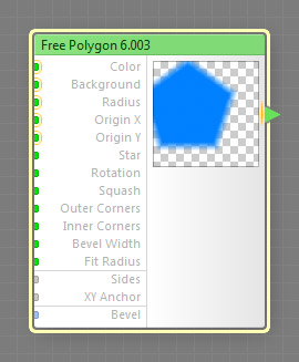
The Free Polygon component generates a polygon or a star with an arbitrary number of sides whose position is not restricted by the image boundaries. The colors of the polygon and the background can be customized using the Color and Background parameters. This is a map component, it can be located in the Patterns category on the Components Bar. This component can output HDR colors.
Free Polygon is a non-seamless component. Its presence in a filter disables the Seamless Tiling checkbox, unless you force-enable it in the Overrides dialog or connect it to so-called “seamlessizer inputs” exclusively. For a seamlessly-tiled analog, try the Polygon component. For more information, see Non-Seamless Components.
Defines the polygon color. This input can accept HDR colors.
Defines the background color. This input can accept HDR colors.
Radius: Map Input
Defines the radius of the circle circumscribed around the polygon. When XY Anchor is set to Default (Size), the actual radius is also affected by the value of the Size slider. Since Radius is a map input, its value can be controlled separately for different image areas by connecting a map component.
Origin X and Y: Map Inputs (HDR)
These inputs define the coordinates of the origin point for the polygon center. The way these coordinates are interpreted is defined by the XY Anchor input. Since Origin X and Origin Y are map inputs, their values can be controlled separately for different image areas by connecting a map component. These inputs can accept HDR colors.
Star: Map Input
Turns the polygon into a star. When Star is zero, the polygon is convex.
Rotation: Map Input
Specifies the angle of rotation in degrees. Since Rotation is a map input, its value can be controlled separately for different image areas by connecting a map component.
Squash: Map Input
Specifies how the polygon is squashed, i.e. the non-uniformity of flattening along the axes. The value of 0 corresponds to the regular polygon, while negative values squash the shape horizontally, and positive values squash it vertically. Since Squash is a map input, its value can be controlled separately for different image areas by connecting a map component to this input.
Outer Corners: Map Input
Defines how rounded the outer corners of the polygon are. With Outer Corners of 0, the corners of the polygon will be sharp, with no rounding. With Outer Corners of 100, the corners will be fully rounded. Since Outer Corners is a map input, its value can be controlled separately for different image areas by connecting a map component to this input.
Inner Corners: Map Input
Defines how rounded the inner corners of the polygon are. With Inner Corners of 0, the corners of the polygon will be sharp, with no rounding. With Inner Corners of 100, the corners will be fully rounded. This parameter has no effect when Star is 0. Since Inner Corners is a map input, its value can be controlled separately for different image areas by connecting a map component to this input.
Bevel Width: Map Input
Defines the width of the polygon bevel. The less the bevel width, the sharper the polygon edges. When Bevel Width is zero, the transition zone between Color and Background disappears completely. When Bevel Width is 100, it fills the entire polygon area. Since Bevel Width is a map input, its value can be controlled separately for different image areas by connecting a map component to this input.
Fit Radius: Map Input
When Fit Radius is turned off, increasing the Outer Corners value for a star will decrease the overall polygon radius. To prevent this, turn Fit Radius on – this way, the star corners will "touch" the circle circumscribed around the polygon. When a map component is connected to this input, the state of the checkbox is determined separately for different image areas by the brightness level of the image supplied by that component. The brightness level of 0 to 50 corresponds to unchecked Fit Radius, and the level of 50 to 100 corresponds to checked Fit Radius.
Adjusts the number of the polygon sides from 3 to 100.
Determines how the coordinate values supplied by Origin X and Origin Y inputs are interpreted. For more information, see How XY Anchor Works.
Bevel: Curve Input
Defines the bevel profile of the polygon (the transition between Color and Background). When Bevel Width is zero, this parameter has no effect. Three predefined bevel profiles are available: Linear, Smooth, and Contours. To customize the bevel profile, connect a curve component to this input.
For best results, the curve connected to the Bevel input should start at 0 and end at 100% – curves like Linear, Step, Gain and Stairs are perfect choices, while curves like Noise or Wave will require additional adjustments or modifications (for example, you can use the Fade component to force the start and end of any curve into desired positions).