This component is obsolete and its use in filters is not recommended. Use the recent version of the component.
Bomber Plus is an advanced version of the Bomber component. In addition to the functionality of the regular Bomber component, Bomber Plus provides the ability to customize the appearance of individual particles via its slave components that expose various internal parameters of the particle (such as its actual size or rotation, random numbers unique for this particle, or the coordinates of the particle center and corners) to the subtree that defines particle appearance – see the 'Examples' section below.
The output of slave components of Bomber Plus changes depending on the particle currently being rendered. This means that you can use them in the subtree of the Particle input to vary any number of inputs in that subtree for each individual particle. For more information, see the section 'Using Slave Components' below. For general information about slave components, see Slave components.
Since individual particle customization is now possible via slave components, some inputs that are present in the regular Bomber component were removed from Bomber Plus as unnecessary:
- Particle 2-5
- Chance 1-5
- Tint Color
- Tint Amount
- Tint Mode
The Bomber Plus is a map component, it can be located in the Patterns category on the Components Bar. Bomber is a discrete component: any filter that uses it is automatically classed as a discrete filter. This component can output HDR colors when HDR Mode is turned on.
HDR Mode
When checked, enables Bomber Plus to support HDR colors but disables certain blending modes for compositing particles.
Particle: Map Input (HDR when HDR Mode is turned on)
This input defines particles to be sprayed. In contrast to the regular Bomber component, Bomber Plus only has a single Particle input: instead of relying on a fixed set of particle subtrees, it allows to create variation in particle appearance via slave components. However, if you still need multiple different Particle subtrees, use a Map Switch component with the Randomizer slave connected to the Selector input of Map Switch.
Particle is the only input in Bomber Plus that can accept connections from the Bomber Plus slave components. Connecting them to any other inputs will have no effect. For more information, see the section 'Using Slave Components' below.
Particle is a so-called 'seamlessizer input' – it can safely accept connections from non-seamless components without preventing the resulting filter from generating seamlessly-tiled results.
When a size-independent component, such as Image, Selection, Color Control, Grayscale Control or Frame is used in the subtree of the Particle input, you need to route this connection through Particle Adapter to ensure correct reaction to the changes of the global Size slider.
Background: Map Input (HDR when HDR Mode is turned on)
Defines the background color or image.
Opacity: Map Input
Defines the opacity of the particles. Lower values make particles more transparent, and Opacity of 0 makes them completely invisible.
Since Opacity is a map Input, it allows you to control the opacity of individual particles separately. When a map component is connected to this input, the opacity of each individual particle is determined by the brightness level of the image supplied by that component. The brightness level defining the particle opacity is sampled at the center of that particle (particles are considered square, regardless of their actual shape.) Black areas correspond to Opacity of 0, white areas to Opacity of 100, and the opacity values in-between are represented by intermediate brightness levels.
The resulting opacity of each particle is also affected by Opacity Chaos, Particle Mode, Layering, Layer Order, Details and Roughness, as well as the alpha channel of the particles themselves.
Size: Map Input
Controls the size of all the particles. With Size of 0, the particles disappear altogether; with Size of 100, the particles occupy the whole area of the corresponding grid cell.
Since Size is a map Input, it allows you to control the size of individual particles separately. When a map component is connected to this input, the size of each individual particle is determined by the brightness level of the image supplied by that component. The brightness level defining the particle size is sampled at the center of that particle (particles are considered square, regardless of their actual shape.) Black areas correspond to Size of 0, white areas to Size of 100, and the size values in-between are represented by intermediate brightness levels.
Rotation: Map Input
Specifies the angle of particle rotation in degrees. Rotation is performed around the center of each particle (the particles are considered square regardless of their actual shape.)
Since Rotation is a map Input, it allows you to control the rotation angle of individual particles separately. When a map component is connected to this input, the rotation angle for each individual particle is determined by the brightness level of the image supplied by that component. The brightness level defining the particle rotation angle is sampled at the center of that particle (particles are considered square, regardless of their actual shape.) Black areas correspond to Rotation of 0, white areas to Rotation of 100, and the angle values in-between are represented by intermediate brightness levels.
Offset H: Map Input
Specifies the amount of horizontal shift. When Offset H is 0, particles are horizontally centered within their grid cells. Positive values move the particles rightwards, while negative values move them leftwards. The particle center can't go beyond the edges of its grid cell.
Since Offset H is a map Input, it allows you to control the amount of shift for individual particles separately. When a map component is connected to this input, the amount of shift for each individual particle is determined by the brightness level of the image supplied by that component. The brightness level defining the particle offset is sampled at the center of that particle (particles are considered square, regardless of their actual shape.) Black areas correspond to Offset H of -100, white areas to Offset H of 100, and the offset values in-between are represented by intermediate brightness levels.
Offset V: Map Input
Specifies the amount of vertical shift. When Offset V is 0, particles are vertically centered within their grid cells. Positive values move the particles downwards, while negative values move them upwards. The particle center can't go beyond the edges of its grid cell.
Since Offset V is a map Input, it allows you to control the amount of shift for individual particles separately. When a map component is connected to this input, the amount of shift for each individual particle is determined by the brightness level of the image supplied by that component. The brightness level defining the particle offset is sampled at the center of that particle (particles are considered square, regardless of their actual shape.) Black areas correspond to Offset V of -100, white areas to Offset V of 100, and the offset values in-between are represented by intermediate brightness levels.
Squash: Map Input
Specifies how the particles are squashed, i.e. the non-uniformity of flattening along the axes. Squashing is performed around the center of each particle (the particles are considered square regardless of their actual shape.) The value of 0 corresponds to the original undistorted particle shape, negative values squash the particles horizontally, and positive values squash them vertically.
Since Squash is a map Input, it allows you to control the amount of squashing for individual particles separately. When a map component is connected to this input, the amount of squashing for each individual particle is determined by the brightness level of the image supplied by that component. The brightness level defining the particle squashing is sampled at the center of that particle (particles are considered square, regardless of their actual shape.) Black areas correspond to Squash of -100, white areas to Squash of 100, and the squashing values in-between are represented by intermediate brightness levels.
Opacity Chaos: Map Input
Defines the amount of randomization applied to the opacity of each particle. With Opacity Chaos of 0, no randomization is applied; Opacity Chaos of 100 corresponds to the highest randomization level.
Since Opacity Chaos is a map Input, it allows you to control the amount of opacity randomization applied to individual particles separately. When a map component is connected to this input, the amount of randomization for each individual particle is determined by the brightness level of the image supplied by that component. The brightness level defining the randomization amount is sampled at the center of that particle (particles are considered square, regardless of their actual shape.) Black areas correspond to Opacity Chaos of 0, white areas to Opacity Chaos of 100, and the randomization values in-between are represented by intermediate brightness levels.
Size Chaos: Map Input
Defines the amount of randomization applied to the size of each particle. With Size Chaos of 0, no randomization is applied; Size Chaos of 100 corresponds to the highest randomization level.
Since Size Chaos is a Map Input, it allows you to control the amount of size randomization applied to individual particles separately. When a map component is connected to this input, the amount of randomization for each individual particle is determined by the brightness level of the image supplied by that component. The brightness level defining the randomization amount is sampled at the center of that particle (particles are considered square, regardless of their actual shape.) Black areas correspond to Size Chaos of 0, white areas to Size Chaos of 100, and the randomization values in-between are represented by intermediate brightness levels.
Rotation Chaos: Map Input
Defines the amount of randomization applied to the rotation angle of each particle. With Rotation Chaos of 0, no randomization is applied; Rotation Chaos of 100 corresponds to the highest randomization level.
Since Rotation Chaos is a map Input, it allows you to control the amount of rotation randomization applied to individual particles separately. When a map component is connected to this input, the amount of randomization for each individual particle is determined by the brightness level of the image supplied by that component. The brightness level defining the randomization amount is sampled at the center of that particle (particles are considered square, regardless of their actual shape.) Black areas correspond to Rotation Chaos of 0, white areas to Rotation Chaos of 100, and the randomization values in-between are represented by intermediate brightness levels.
H Chaos: Map Input
Defines the amount of randomization applied to the horizontal shift of each particle. With H Chaos of 0, no randomization is applied; H Chaos of 100 corresponds to the highest randomization level.
Since H Chaos is a map Input, it allows you to control the amount of shift randomization applied to individual particles separately. When a map component is connected to this input, the amount of randomization for each individual particle is determined by the brightness level of the image supplied by that component. The brightness level defining the randomization amount is sampled at the center of that particle (particles are considered square, regardless of their actual shape.) Black areas correspond to H Chaos of 0, white areas to H Chaos of 100, and the randomization values in-between are represented by intermediate brightness levels.
V Chaos: Map Input
Defines the amount of randomization applied to the vertical shift of each particle. With V Chaos of 0, no randomization is applied; V Chaos of 100 corresponds to the highest randomization level.
Since V Chaos is a map Input, it allows you to control the amount of shift randomization applied to individual particles separately. When a map component is connected to this input, the amount of randomization for each individual particle is determined by the brightness level of the image supplied by that component. The brightness level defining the randomization amount is sampled at the center of that particle (particles are considered square, regardless of their actual shape.) Black areas correspond to V Chaos of 0, white areas to V Chaos of 100, and the randomization values in-between are represented by intermediate brightness levels.
Squash Chaos: Map Input
Defines the amount of randomization applied to the squashing of each particle. With Squash Chaos of 0, no randomization is applied; Squash Chaos of 100 corresponds to the highest randomization level.
Since Squash Chaos is a map Input, it allows you to control the amount of squashing randomization applied to individual particles separately. When a map component is connected to this input, the amount of randomization for each individual particle is determined by the brightness level of the image supplied by that component. The brightness level defining the randomization amount is sampled at the center of that particle (particles are considered square, regardless of their actual shape.) Black areas correspond to Squash Chaos of 0, white areas to Squash Chaos of 100, and the randomization values in-between are represented by intermediate brightness levels.
Roughness: Map Input
Adjusts the roughness of the particle pattern. Technically, Roughness defines the relative transparency of the particle layers (the number of the layers is controlled by the Details parameter). Roughness of 0 sets all layers but the first to zero transparency, which is equivalent to setting the Details parameter to 0. Low roughness values give layers with large-grained grids more visibility. Higher roughness values increase the visibility of layers with smaller-grained grids, making the resulting pattern rougher. Roughness has no effect when Details is set to 0, because in this case only one particle layer is visible. The relative transparency of the particle layers is also affected by the Layering input.
Since Roughness is a map Input, its value can be controlled separately for different image areas by connecting a map component to this input. Lower Roughness can speed up the rendering – when the visibility of smaller-grained particle layers is very close to zero, they are 'turned off' to save the rendering time.
Depth Map: Map-only Input (HDR)
Defines the height (Z-order) of particles according to the brightness level of the image supplied by the connected component: dark areas correspond to low height values, and bright areas correspond to high height values. If no component is connected to the Depth map input, all particles are considered to lay on the same level, and Depth Map has no effect. This input can accept HDR colors.
Specifies the blending mode used for blending new particles with previously rendered particles and the Background. The list of the blending modes and their functionality are the same as in the Blend component (or the Blend HDR component when HDR Mode is turned on.)
Specifies the way the Details and Roughness inputs affect the relative transparency of particle layers.
The Balanced mode calculates the layer transparencies using the same algorithm as used in fractal noises such as Perlin Noise. This mode is recommended for making noise-like patterns and for use in situations where changing the Roughness value should not significantly affect the average brightness of the resulting image.
Both Simple and Simple (Normalized) modes arrange the relative transparencies of the particle layers in a linear progression, where the first layer (one with the largest-grained grid) is always fully opaque, and the opacity of each subsequent layer decreases by a linear decrement which depends on the Roughness value (and also, in case of Simple (Normalized), on the Details value.) The difference between Simple and Simple (Normalized) is that the former doesn't normalize the transparencies, while the latter normalizes them based on the actual number of visible particle layers (determined by the Details input.)
Specifies the blending order of the particle layers: Small on top or Big on top. When Small on top is selected, the particle layers with smaller-grained grids are successively placed over the layers with larger grids, and vice versa. Note that Big and Small refer to the cell size of the particle grid, not to the actual size of the particle itself.
Specifies the way of sorting the particles: Across Layers or Within Layers. When Across Layers is selected, the particles are sorted regardless of the layer they belong to. When Within Layers is selected, the particles are first separated by layers, and then sorted within their layer only. Sorting itself is performed according to the Depth Map value; if no component is connected to the Depth map input, all particles are considered to lay on the same level, and Depth Sorting has no effect.
Adjusts the particle pattern complexity. Technically, Details sets the number of the particle layers that form the resulting pattern. Details of 0 means only the first layer is visible, 20 means 3 layers, and 100 means 11 layers are visible. Values such as 27 mean that first three layers have full visibility, and the fourth one has 70% visibility. Details has no effect when Roughness is set to 0, because in this case only the first layer has 100% visibility no matter how many layers are active.
Large Details value leads to longer rendering times because it increases the number of particle layers, and therefore particles, to calculate. For example, when Details is 0, only one particle layer is rendered. When Details is 100, eleven layers are rendered which can slow down the rendering up to eleven times. So if you don't need a high number of layers, you can lower it to make rendering quicker.
Specifies the number of cells in the layer with the largest-grained particle grid. The subsequent grid will have four times less cells than the first one, and so on. The actual number of repetitions within the output image is also affected by the global Size parameter and the image dimensions.
Specifies the number of particles per grid cell of the particle layer. The actual number of the particles in a single cell equals the square of the Density value – for example, the Density of 2 gives 4 particles per cell, Density of 3 gives 9 particles per cell, etc. When Density is set to a high value, particles may completely obscure the Background color or image, so if you want the background to be visible, make sure to lower Size and Size Chaos values. Higher Density values increase the rendering time.
Variation, technically known as random seed, affects the random aspects of the component which cannot be controlled directly: it randomizes the opacity, size, rotation, squashing and shift of the particles when Opacity Chaos, Size Chaos, Rotation Chaos, H Chaos, V Chaos and Squash Chaos are set to non-zero. The randomization is also affected by the global Variation value. For more information, see How Variation Works.
Slave Components
These buttons create slave components linked to the currently selected Bomber Plus. You can have multiple copies of each slave component.
Add Randomizer
Adds a Randomizer slave component that outputs a normalized random value (converted to color) that is unique for each particle. You can create multiple copies of Randomizer, so if you need multiple random values to build or modify the particle subtree, you can use multiple Randomizers with different Variation settings (i.e. random seeds).
Add Size
Adds a Size slave component that outputs a grayscale value within the range of 0...1 that represents the actual particle size, after the Size and Size Chaos parameters have been applied. Does not take into account particle scaling due to fractal layering. It allows you to modify the particle subtree based on how large the particle is (on its layer, not in absolute terms).
Add Rotation
Adds a Rotation slave component that outputs a grayscale value within the range of 0...1 that represents the actual particle rotation, after the Rotation and Rotation Chaos parameters have been applied. It allows you to modify the particle subtree based on the rotation angle of the particle.
Add Squash
Adds a Squash slave component that outputs a grayscale value within the range of 0...1 that represents the actual particle 'squashedness' or flatness, after the Squash and Squash Chaos parameters have been applied. It allows you to modify the particle subtree based on how thinly-squashed the particle is.
Add Center X
Adds a Center X slave component that outputs an HDR grayscale value representing the actual X coordinate of the actual particle center, after all transformations, offsets and chaos have been applied. The main use of Center X and Center Y slave components is to lookup a value or color from a custom map via the Lookup component and use it to customize the particle (so-called 'lookup technique').
Add Center Y
Adds a Center Y slave component that outputs an HDR grayscale value representing the actual Y coordinate of the actual particle center, after all transformations, offsets and chaos have been applied.
Add Corner X
Adds a Corner X slave component that outputs an HDR grayscale value representing the actual X coordinate of a specified corner of the particle, after all transformations, offsets and chaos have been applied. Corner X and Corner Y slave components are useful for looking up values or colors from a custom map at the particle corners or at other points within the particle via the Lookup component to create artistic effects.
Add Corner Y
Adds a Corner Y slave component that outputs an HDR grayscale value representing the actual Y coordinate of a specified corner of the particle, after all transformations, offsets and chaos have been applied.
Add Layer
Adds a Layer slave component that outputs a raw HDR grayscale value representing the number of the fractal layer the particle is placed on. Please refer to the help article for Bomber for more information on particle layering.
Add Normalized Layer
Adds a Normalized Layer slave component that outputs a normalized value representing the number of the fractal layer (or octave) the particle is placed on, converted to color. This slave can be useful for creating effects like 'particles in the fog' where particles residing on lower or higher layers are modified using some kind of color correction.
Using Slave Components
Slave components of Bomber Plus work properly only when the following conditions are met:
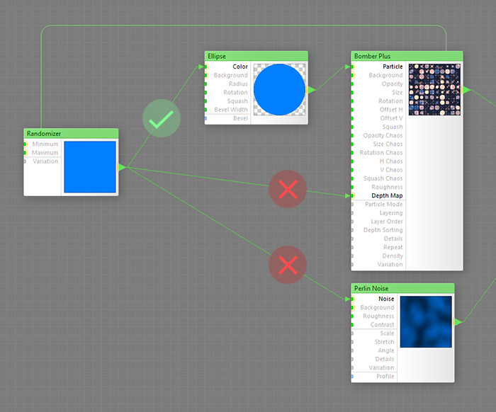
First, any slave components must be connected to the subtree of their master's Particle input, otherwise they will have no effect. The Particle input is the only input in Bomber Plus that generates element data for slaves during sampling.
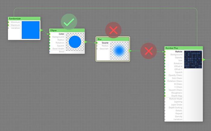
And second, there must be no bitmap-based components between the slave and the Particle input. Bitmap-based components (such as Blur shown in the example below) kill the element data sent to slaves by their master, and thus cannot be used in slave-to-master connections.
Nesting
Like Loop or any other slave-supporting component, Bomber Plus is nestable: it can be nested within a subtree of another slave-supporting component, or have another slave-supporting component inside its Particle subtree, or both at the same time.
Examples
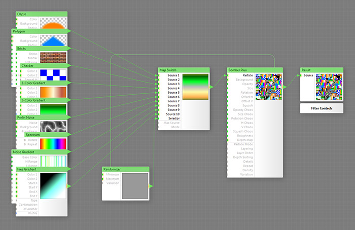
This simple example shows a Map Switch with a Randomizer slave plugged into its Selector input, which selects any of the 10 single-component subtrees at random:
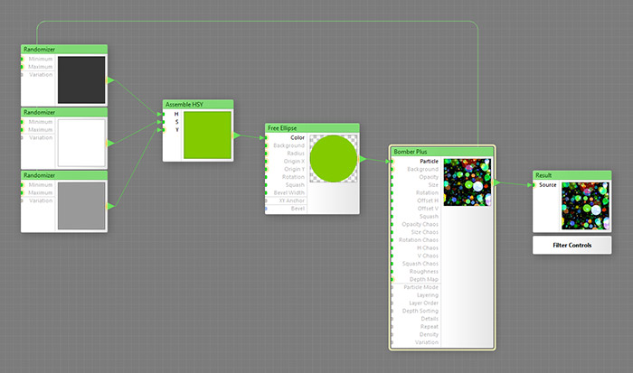
The next example uses three Randomizer slaves to assemble a random HSY color, which is then assigned to each particle:
In the next example, particles are rotated randomly and get their color based on their rotation: particles whose rotation angle is close to 90 degrees are bright, and the rest of them are dark:
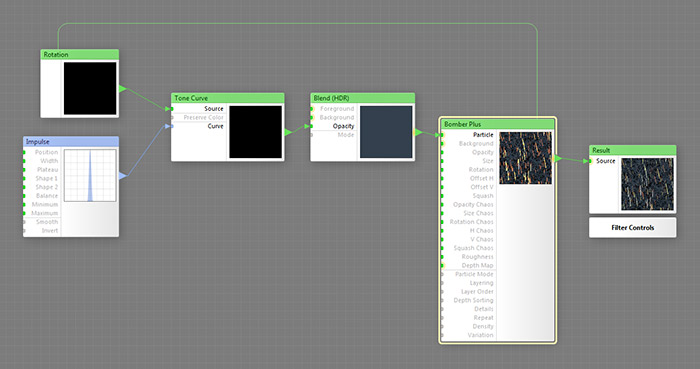
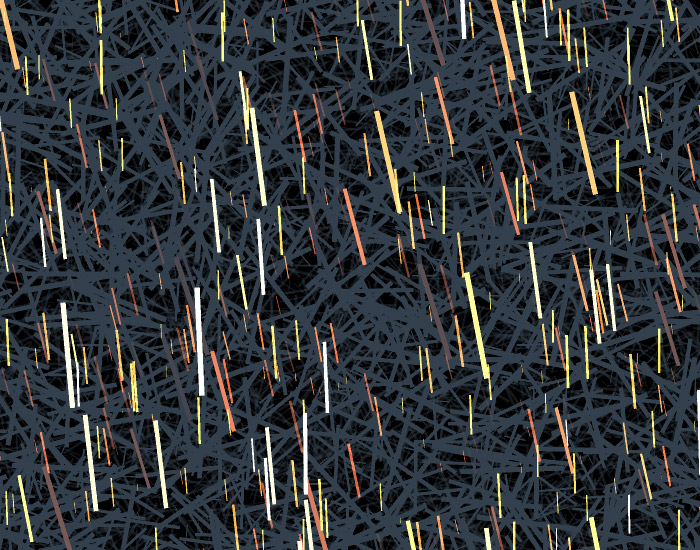
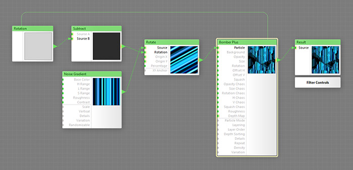
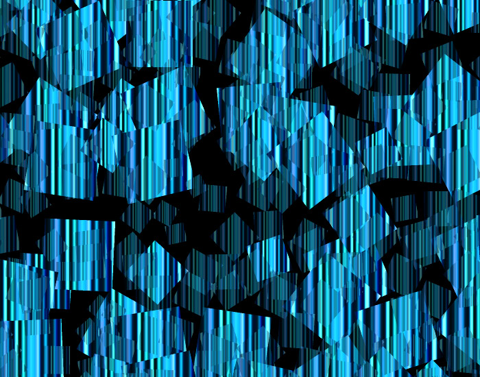
Here's another cool trick with the Rotation slave. The particles themselves are rotated randomly, but the pattern always stays vertical. This is because particle rotation is compensated by rotating the pattern in the opposite direction by the same amount:
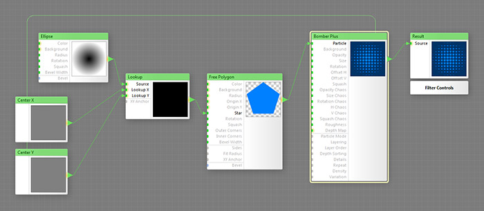
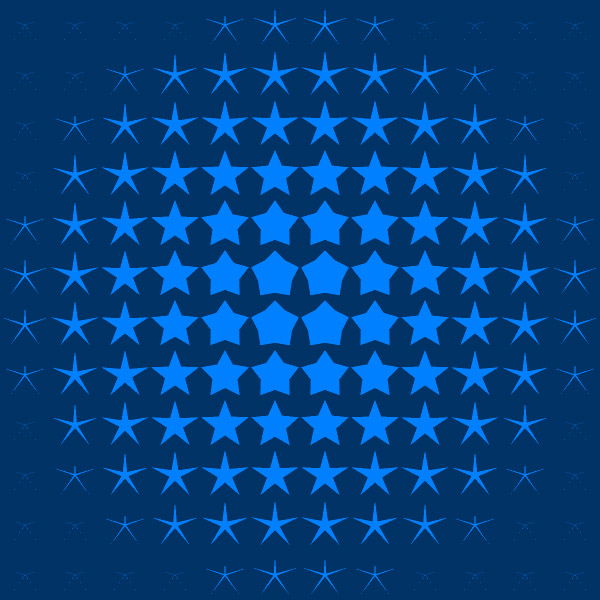
The next example demonstrates the 'lookup technique', enabled by Corner X / Y and Center X / Y slave components, which allows you to customize some aspect of a particle based on an external map. It works as follows: the Center X and Center Y slaves output particle center coordinates; both coordinates are plugged into a Lookup component; the Lookup component samples the radial gradient at these coordinates; and finally, the sampled value defines the ray sharpness of each individual star. To sum up, a custom map (the radial gradient) defines an aspect of the particle (ray sharpness):
One more example of the lookup technique. This time, we are sampling colors at the particle corners and interpolate them across each particle individually via a custom 4-point gradient. The resulting effect may be very useful for builders of various artistic / painterly effects: